How PWM Turns Digital Pins Into Precision Pulse Controllers
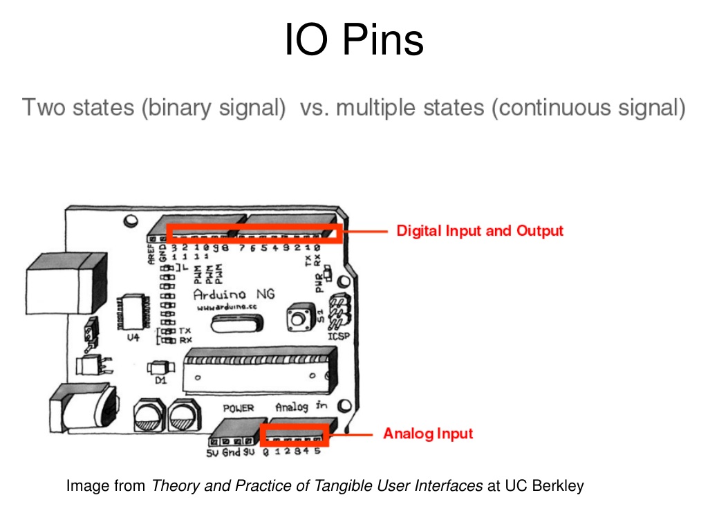
Digital IO Pins With PWM Explained
When you think of a microcontroller’s digital output pin, the image that often comes to mind is a simple on/off switch. In reality, many of these pins can deliver a far richer signal: a pulse‑width‑modulated waveform that behaves like a dimmer switch, a speed controller, or a virtual analog output. In this article we’ll unpack how Pulse‑Width Modulation (PWM) works, how it’s implemented on digital IO pins, and why it’s indispensable in everyday electronics projects.
What Is Pulse‑Width Modulation?
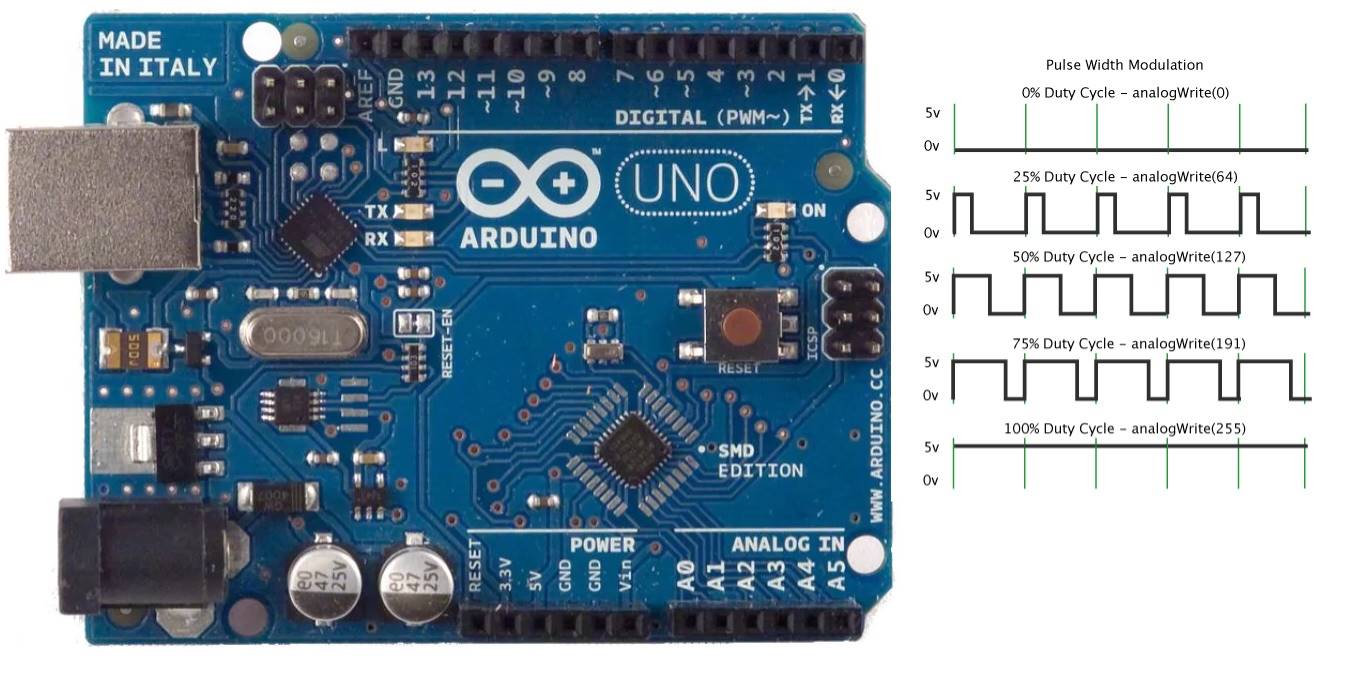
PWM is a technique that encodes an analog value into a series of digital pulses. Each pulse has a fixed period, but the time it stays high (the duty cycle) varies from 0 % to 100 %. By averaging the high and low states over many cycles, a receiving circuit perceives a steady voltage proportional to the duty cycle.
In formula form:
Effective Voltage ≈ Vcc × (Duty % / 100)
Because the actual voltage never deviates from the supply voltage, PWM avoids the heat loss that would otherwise occur in a linear analog regulator.
Digital Pins as PWM Engines
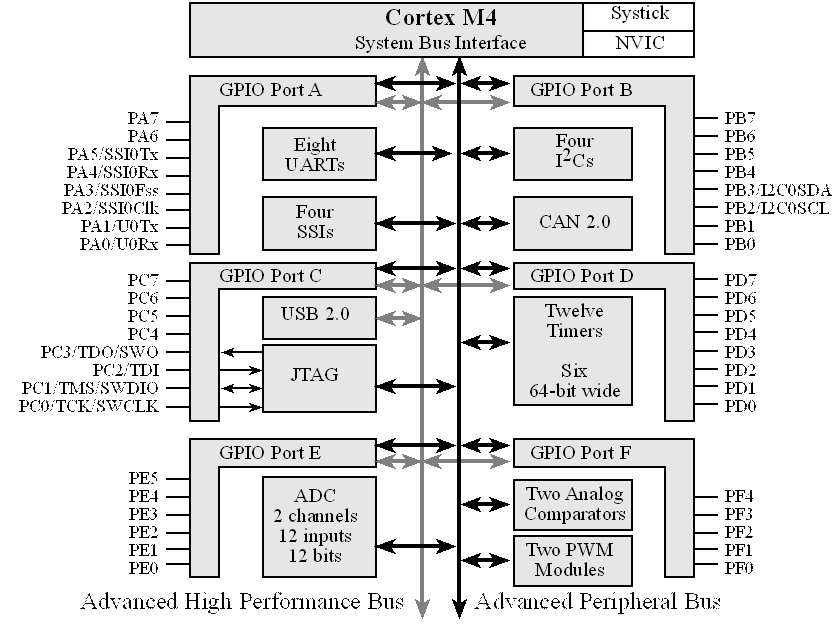
Most microcontrollers expose a handful of dedicated PWM outputs. These pins are engineered to toggle at high speeds, driven by a timer peripheral. When you write a value to a PWM register, the microcontroller’s hardware takes over and handles the toggling automatically, freeing the CPU for other tasks.
On the contrary, software‑based PWM (bit‑banging) uses a general‑purpose digital pin. The CPU manually sets the pin high and low with precise timing delays. While this works on low‑frequency tasks, it consumes CPU cycles and is sensitive to interrupts.
Hardware PWM vs. Software PWM
- Hardware PWM offers consistent frequency, low CPU load, and high resolution.
- Software PWM is flexible in pin selection but limited in frequency and resolution.
Choosing between them depends on project constraints—speed, pin count, and processing power.
Typical Microcontroller Support
Every popular family has its own PWM API:
- Arduino AVR boards:
analogWrite(pin, value)wherevalueis 0–255. - STM32: TIM peripherals with CCR registers; the frequency is set by the prescaler.
- ESP32: LEDC module that supports up to 16 channels with 16‑bit resolution.
In each case, the developer writes a duty‑cycle value; the hardware updates the output accordingly.
Configuring PWM on an Arduino
Let’s walk through a quick example. Suppose we want to dim an LED:
int ledPin = 9; // PWM pinvoid setup() {
pinMode(ledPin, OUTPUT);
}
void loop() {
for (int i = 0; i <= 255; i++) {
analogWrite(ledPin, i); // Increase brightness
delay(10);
}
for (int i = 255; i >= 0; i--) {
analogWrite(ledPin, i); // Decrease brightness
delay(10);
}
}
The analogWrite() function writes a 0‑to‑255 value that the AVR hardware maps to a duty cycle between 0 % and 100 %. Because the pin toggles at ~490 Hz on most boards, the human eye sees a smooth fade.
Timing and Frequency Considerations
The PWM frequency determines how often the pulse repeats. Too low, and you’ll see flicker or audible noise in motors. Too high, and the pin may exceed the hardware’s toggling capability.
Key guidelines:
- LED dimming: 100 Hz–1 kHz is usually enough to avoid visible flicker.
- Motor control: 1 kHz–20 kHz keeps the motor smooth while preventing audible whine.
- Audio output: 20 kHz–50 kHz is needed for high‑fidelity signals.
Most microcontrollers let you set the timer prescaler and period to achieve the desired frequency.
Common Applications
Digital IO pins with PWM are the backbone of many everyday gadgets:
- LED brightness control – simple fade in/out or RGB mixing.
- Servo positioning – the pulse width encodes the arm angle.
- DC motor speed regulation – the duty cycle translates to average voltage.
- Audio generation – square‑wave tones or low‑frequency oscillators.
- Power delivery – controlled charging or load balancing.
Each use case demands careful selection of frequency, resolution, and filtering.
Troubleshooting Tips
If your PWM output isn’t behaving as expected, try these steps:
- Verify the pin is configured as OUTPUT.
- Check that you’re using a dedicated PWM pin; general‑purpose pins may lack hardware support.
- Ensure the timer’s prescaler and period produce the desired frequency.
- Use an oscilloscope to confirm the waveform shape.
- Add a low‑pass RC filter if you need a smoother analog signal.
Hardware limitations, such as maximum toggle rates, can also constrain performance.
Frequently Asked Questions
Q1: Can PWM be used on any digital pin?
A1: Only pins with dedicated timer modules support hardware PWM. Other pins can emulate PWM via software but with lower performance.
Q2: Is PWM safe for driving high‑current motors?
A2: Yes, provided the pin is connected to a driver circuit (e.g., MOSFET) that handles the current, as the microcontroller itself can only source milliamps.
Q3: What resolution can I expect from an Arduino PWM?
A3: The AVR pins provide 8‑bit resolution (256 steps). ESP32’s LEDC module supports up to 16‑bit, yielding 65 536 steps.
Q4: How do I reduce audible noise in motors using PWM?
A4: Increase the PWM frequency beyond the audible range (~20 kHz) and add a filter if necessary.
![The Full Arduino Uno Pinout Guide [including diagram]](https://images.prismic.io/circuito/e57c56f68189f03145726786306d6a8ca7168571_arduino-uno-pinout-digital-pins-pwm-1.png?auto=compress,format)